Part 3 of 3: Superposition of Motion Profiles
Introduction
This is the final paper of three delving into advanced electronic gearing topics in motion control. The first two, Tension Control on Spindle Wheel and Positional Correction on Color Print Rollers in Offset Printing, dealt with both low and high bandwidth corrections by correcting for frequency and phase.
This paper will cover how to apply electronic gearing to superimpose two motion profiles for a single axis. Three different examples will be discussed showing the many different applications where adding two motion profiles together can simplify the system’s design.
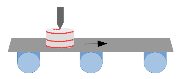
Example 1: Writing on a cake that is moving on a conveyor

Figure 1: Cake writing on a moving conveyor
Problem Definition
Figure 1 shows a cake moving horizontally on a conveyor. The frosting dispenser above the cake needs to write “Happy Birthday” as the cake moves along. In order for the final image to be orthogonal, the actual profile needs to be skewed, as shown in Figure 2.

Figure 2: “Happy Birthday” motion profile in absolute coordinates
The problem can be simplified by breaking down the system into two reference frames: the cake’s coordinates, and the absolute coordinates. The dispenser must ultimately move according to the absolute coordinates of the system, but “Happy Birthday” must be drawn according to the cake’s coordinates as seen in Figure 3.

Figure 3: “Happy Birthday” motion profile in cake coordinates
Resolution
Electronic gearing allows for a given axis to superimpose its coded profile with the profile of a secondary encoder input.
In this example, there are 2 axes, A and B for the frosting dispenser, and an independent conveyor system. In this case, the A axis for the dispenser is in the same direction as the conveyor. This means that the absolute profile is the sum of writing “Happy Birthday” in the cake’s coordinate system and the conveyor movement.
Using a DMC-4020 motion controller from Galil, the following code would provide a simplified solution. In Code 1, the A and B axes represent the cake dispenser, respectively, while the auxiliary A axis is the conveyor system’s position.
#gear
GAA=DA; 'Dispenser’s A axis geared to conveyor feedback
GRA=ratio; 'Resolution ratio of conveyor and dispenser’s A encoders
#write
'Motion code to write "Happy Birthday"
'Written with Axes A and B operating in the cake's coordinate axes
EN; 'End routine
Code 1: DMC-4020 code to gear cake-writing dispenser to conveyor
This solution allows for the programmer to separate the code of the cake’s coordinate profile into a stand-alone routine.
Example 2: Scanning an object with a helical motion profile

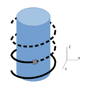
Figure 4: Helical profile to scan cylindrical object
Problem Definition
Figure 4 shows a sensor that needs to move in a helical profile to scan a cylindrical object. The sensor is controlled by three axes in the X, Y, Z Cartesian coordinate system.
A typical 3-axis helical motion requires 2 different components: the circle profile for X and Y, and the linear profile for Z. When programming it as such, the developer must take into account all differences in speed and acceleration for the circle and the linear axis to be able to maintain the exact spacing required for the helical motion profile. This is further complicated when speeds are changed during the helical move itself.
Resolution
With electronic gearing, not only can a particular axis be geared to another axis, but an axis may also be geared to a vector move on a plane. This allows for the vertical Z profile to be correctly synced to the circular X and Y profiles. The benefit this provides is the ability to properly coordinate the accelerations and speeds of both the circular and linear components. The effect is that changes in the vector speed automatically apply to the geared vertical Z profile.
Code 2 is used on a Galil DMC-4030 motion controller where the axes A, B, and C represent the X, Y, and Z axes in Figure 4. The DMC-4030’s C axis is geared to the S vector plane – the 2 dimensional vector plane of axes A and B.
#helix
GAC=S; 'Gear axis C to vector plane S
GRC=ratio; 'Sets vertical spacing of helical motion
#circle
VMAB; 'Declare axes A and B for vector plane S
CR radius,startAng,angToDrw; 'Draw circles in vector plane S
VE; 'End vector segment
BGS; 'Begin vector move
EN; 'End routine
Code 2: Helical motion for scanning object
Example 3: Profile positional move with added sinusoidal motion
Problem Definition
In some applications, a smaller cyclic, pecking, or back-n-forth motion is needed on top of a linear move. For example, a grinding application may require a grinder to cyclically move in a sinusoidal pattern as it moves down a material.
Following the same structure as in the previous two examples, this problem can be broken down in to two separate profiles: the point to point move, and the sinusoidal motion. The challenge here is that there are two profiles to superimpose, but only one axis. In previous examples, an axis was geared to another physical encoder or vector plane.
Resolution
The functionality of virtual axes can also be applied to electronic gearing. A virtual axis, juxtaposed to a real axis, is an imaginary axis that has the ability to profile just like a real axis. However, the virtual axis has no associated I/O; it does not read actual position, nor does it have a commanded output with a PID filter. Its purpose is to provide the ability to use it with certain modes that may require only the profiling ability of an axis, without the actual control of a motor. By using a virtual axis, this function can be accomplished without using an additional real axis.
For the DMC-40x0 motion controller, two virtual axes are available: M and N. Therefore, the real axis A can profile the sinusoidal motion and the virtual axis M can profile the linear move. Axis A is geared to the virtual axis M with the following commands.
#gear
GAA=M; 'Gear axis A to virtual axis M
GRA=ratio; 'Typically a 1 to 1 ratio
Code 3: Gear real axis to virtual axis
The M axis’ point to point move is commanded in the same manner as a real axis.
#virt
PRM=position; 'Positional move relative to current position
SPM=speed; 'Speed of virtual axis
Code 4: Command virtual axis for linear move
Figure 5 shows the profiled sinusoidal motion on axis A, the point to point profile on virtual axis M, and the final superimposed result – the actual motion of the grinder.

Figure 5: Superimposed move of grinder
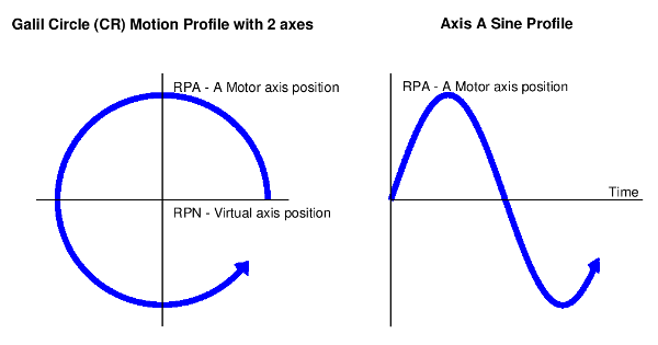
The final challenge is profiling the sinusoidal motion. This can be simplified with vector mode and the circle command (CR) that was introduced in Example 2. To draw a circle in the XY Cartesian plane, the X must profile a cosine wave, while the Y profiles a sine wave. Since only the sine wave is desired, a second axis can be used to initialize vector mode only. The second virtual axis, N, is used for that purpose. In this case, the virtual axis allows the user to satisfy the requirements of initializing vector mode to draw the circle, without dedicating a real axis. Figure 6 shows the XY Cartesian plot of a circle drawn with virtual axis N and real axis A compared with the motor position versus time plot of real axis A. The end result of a profiled sine wave is clearly visible.

Figure 6: Generate sine profile on DMC-40x0
Code 5 is used to complete the sinusoidal profile of the A axis and begin both the sinusoidal motion and the linear movement of the grinder.
#sine
amp=100; 'Amplitude of sinusoidal motion
freq=5; 'Frequency of sine profile
pi=3.1416; 'Constant pi
rate=freq*amp*pi*2; 'Calculate commanded speed to achieve amp and freq
duration=5*360; 'Total degrees of sine wave (5 full cycles)
VMNA; 'Declare vector mode with N and A axes
VSS=rate; 'Set vector speed
CR amp,0,duration; 'A axis draws sine wave for a given duration
VE; 'End vector segment
#begin
BGS; 'Begin sinusoidal movement
BGM; 'Begin point to point movement
EN; 'End routine
Code 5: Profile sinusoidal movement
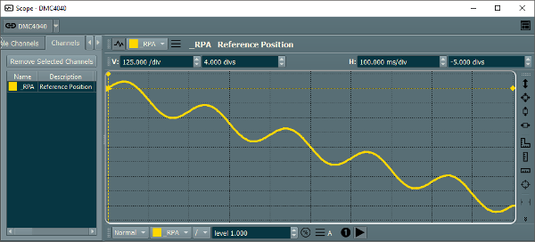
Figure 7 shows the actual profiled output for axis A on the DMC-40x0 motion controller.

Figure 7: Actual profile of grinder
Conclusion
As shown in the above examples, complex motion can be broken down into two simplified, superimposed motion profiles by using the functionality of electronic gearing. The examples show the variety of applications that can benefit from the features of electronic gearing. As demonstrated, electronic gearing is not just limited to only real axes geared to each other, but can be expanded to include independent system feedback, 3-D profile, or other non-intuitive profiles that can be broken down into multiple profiles superimposed together.
For further questions about electronic gearing or other topics, contact a Galil Applications Engineer at (916) 626-0101, or by email at support@galil.com.

